2024 Release Notes (Preview)
A Public BETA for Slabsmith 2024 will be available very soon. It will install side by side with your current version and you can use either one. Note: You need to be current on your maintenence to use the 2024 BETA version.
*** 2024 Youtube videos here ***
In 2024 there are important changes in:
- Scanner support
- Calibration
- Slab Maker
- Perfect Match
There is also new beta Report module which will be included. We will be looking for suggestions for new Reports from customers and then add popular requests as we go.
Scanner support
There are 3 levels of scanner support available in the 2024 release..
- Level 1 – We have written a direct interface for scanners which allows the user to treat the scanner as a big camera. The workflow is exactly the same as using a camera. You select the camera button and the scanner takes a photo, and it appears on the screen in Slabsmith. We will provide this interface to any scanner company and have already provided it to a new scanner company entering the market.
- Level 2 – Calibrating the scanner in Slabsmith Calibration. Currently this is working quite well with Horus. The calibration establishes the pixel scale of the scanner and a fixed zero location for using the scanner with hard stops. Location targets also work with this method. In practice it works much like Level 1, but instead of pushing the camera button to activate the camera and receive the data, we open a “File Open” dialog and select the most recent scan. Everything else works exactly like using Slabsmith with a regular camera, so you have full workflow compatibility and functions.
- Level 3 – The Scanner API. This API has been successfully used with our customers by both Taglio and Horus. The method involves a queueing directory. The required files and info are copied into a queueing directory by the scanner. Slabsmith polls this directly and when we see new files, we create a record in Slab Maker based on the files in the queueing directory. This does not give you as much control as the other two levels of scanner interface.
Note: Taglio has recently decided to stop supporting the Level 3 option, and they have also changed their image storage method which prevents us from using the Level 2 integration which worked previously. This means that Taglio scanners do not currently work with Slabsmith.
Calibration
Calibration has been completely re-written to make calibrating cameras/scanners easier
- Once and done 0,0 setting. The 0,0 test cut on any particular A-frame or Scanner that is needed after a calibration only has to be completed once.After dialing in the 0,0 once, calibration remembers the position relative to the lower left validation target. After completing a calibration just “Apply the zero offset and no need to do a 0,0 test cut and adjustment after doing it once.
We do recommend using the hard validation targets that we have available to they can be permanently mounted on the A-frame and cleaned as needed. They are made out of the same material as the large calibration targets.
As mentioned below in the Slab Maker section, calibrations in total should need to be done much less often as Slab Maker will also automatically correct for minor camera movements.
The upshot to this, is that after completing the 0,0 test once, you should not have to do it again for subsequent calibrations.
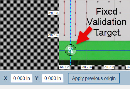
Calibration automatically selects the lower left fixed validation target as a known immovable point. 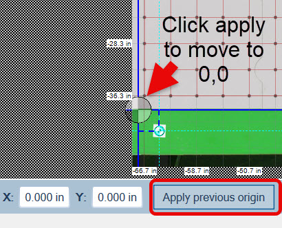
After the first calibration and having adjusted the 0,0 to the correct position you don’t have to adjust the 0,0 again. Just select “Apply previous origin” and it will place the zero in the correct place for the A-frame. - Added a “Two point” calibration function. (turned on in the Admin). We are using this with Horus scanner.
Slab Maker
- Automatic corrections for camera movement. This works by re-aligning the image with the two validation targets. This should work well even for relatively large camera movements. We do report the amount of correction required to make the alignment at the top of Slab Makers window, but we can allow for quite large camera shifts without the need to recalibrate.
- Masking of sections of the A-frame / Scanner. You can establish permanent masks for areas that should never be treated as a slab during separation from the background. For instance you can place a mask on the slab rests, and they will never again be considered part of a slab. This reduces the “touch up” to get a perfect slab separation.
Perfect Match
Significant changes to the interface and operation to both simplify and speed layouts while providing even more 3D facility. There are actually less individual commands but more functionality.
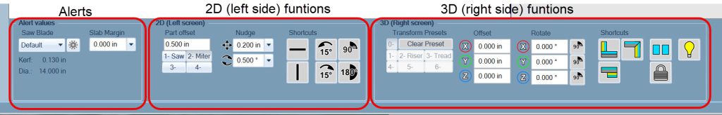
- New “Movement Panel” at the bottom of the screen. This is split into 3 areas.
-
- Alerts –
- *Red* alert when the parts are closer than the Saw blade kerf value.
- *Yellow* alerts for parts closer than the current 2D part offset or when a part is closer than the “Slab Margin” to the slab edge.
- 2D (left side) – Includes:
- The current part offset values. Up to 4 values may be saved and named.
- The nudge (xy and rotation) values
- Shortcuts – buttons for the most common 2D commands
- “3D” (right side) – Includes:
- Transform Presets. This provides a place to save presets for 3D transforms of the parts. The can be saved and renamed. The number on the preset button is also the shortcut key. In the example below, you can assign a Riser by selecting the “2” key.
- Ability to move the part any amount in XYZ or to any rotation angle around the XYZ axis.
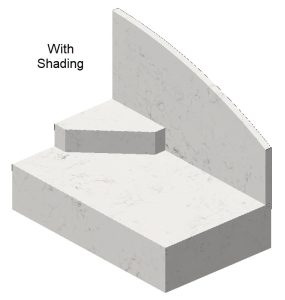
- Shortcuts – buttons for common transforms (Splash, Waterfall, Buildup), a “Reset button” (puts part back in original location) a “Lock” button to lock a part in place so that it can’t be moved and a “Lighting” button which turns on shading of the 3D part for a presentation view of the finished part that is easier to decifer.
 See Video below…
- Alerts –
Working with the parts on the screen
- “2D” (left screen) operation has less commands. It’s faster and simpler.
- “Snap” mode is no longer a selectable mode. You are always in Snap mode. If you select an edge of a part and drag it near the edge of another part, it will snap to the second part at the specified part offset distance.
- If you select and drag from the middle of a part, you will simply move the part to wherever you drag it.
- Added a color checker function to highlight areas of the slabs that are likely to match in color. (it also includes a calibration “trust” overlay to show you areas with problems if the customer does not have a good lighting calibration)
- 3D (Right Screen) operation has also been simplified with increased functionality.
- As in 2D, you can snap to parts together by simply clicking and dragging one edge to another edge. Even if the edge is already in 3D space. This replaces the “Orient” command in the current version. Effectively you are always in the Orient AND the Snap command.
- When you drag one edge to the other you establish a relationship between the two parts. They start co-planer, but you can then apply any of the 3D commands to this relationship. (Backsplash, Waterfall, etc.) or manually set any of the translation/rotation offsets by clicking on the gnomon and typing in a value.
- If you click the middle of a part, you can drag it anywhere in its current plane. (move parts randomly on the right screen)
- Parts are displayed with a thickness and a dark back without placing them over a slab. This makes it easier to create a 3D part.
- A gnomon is displayed on the part when snapped to another part and you can move it from its base snap position in XYZ in the Offset controls at the bottom of the screen. You can Also do a rotation around XYZ to any angle.
- You can drag/rotate by clicking on the gnomon and moving your mouse
- Added 6 – 3D transform presets. This is a fancy way to save common 3D transforms (think of having a set of stairs, with one transform being the riser, and another being the tread transform) Put the numbers in once, then just select the preset when needed.
- 3D export of layout (.GLB file) which can be downloaded by the fabricator’s customer with a link to a page on the Slabsmith website that they can view the job in 3D and Augmented Reality with their phone.
- A Digital sign off sheet and job viewer. There will be a “Send to SlabCloud” option on the 3D export which will provide a one click link to view the job in 3D and AR and to get a customer sign-off and acceptance of the job. Slabsmith customers will get a free trial of this feature from SlabCloud.
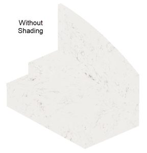
- A toggle to do shading on 3D parts to make them easier to see. Particularly with white materials.
- Both sides
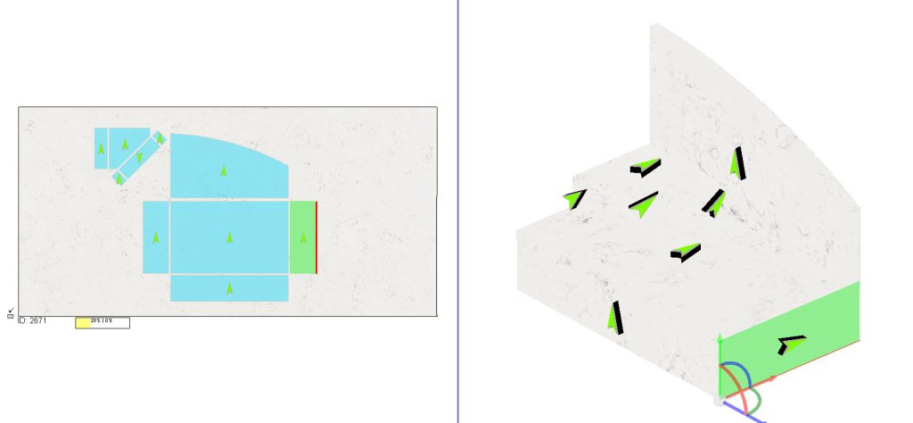
- Added orientation arrows to both sides. This helps you determine where the same part is on both sides and it’s orientation in the 3D model relative to the left side parts.
- Added orientation arrows to both sides. This helps you determine where the same part is on both sides and it’s orientation in the 3D model relative to the left side parts.