The

slab scanner
A collaberation between
Slabsmith & Helios

This web page was designed to provide you with the knowledge to make an informed decision when purchasing a slab scanner.
You will learn how scanners work, and why the STONE VISION scanner is the Next Generation of slab scanners.
How Scanners work
Line scanner cameras
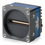 All current scanners use a line scanner. A line scanner is a special camera that scans a single line, one pixel wide. To capture a larger picture, the camera is moved over surface while continuously capturing individual lines. When the scan lines are combined, this produces the larger image.
Line scanners are typically used in machine vision applications. When the camera is combined with the correct lens, and the camera is properly aligned, the majority but not all of the distortion along the scan line can be accommodated by the lens.
Slab scanners use a combination of two line scanners to produce the final image. One mounted directly over the other. The field of view of the cameras overlaps in the middle. When a scan is completed, there are two separate images, one from each camera. These images need to be “Stiched” together to produce a single final image.
While the distortion correction in the line scan axis on a single camera is in large part corrected by the correct lens and flat field correction, this does correct for potential mis-aligned top and bottom cameras. This often leads to time and difficult setup and calibration in the field if the scanner needs it. This issue is automatically corrected with Slabsmith’s implentation as will be detailed below.
Stitching and Parallax
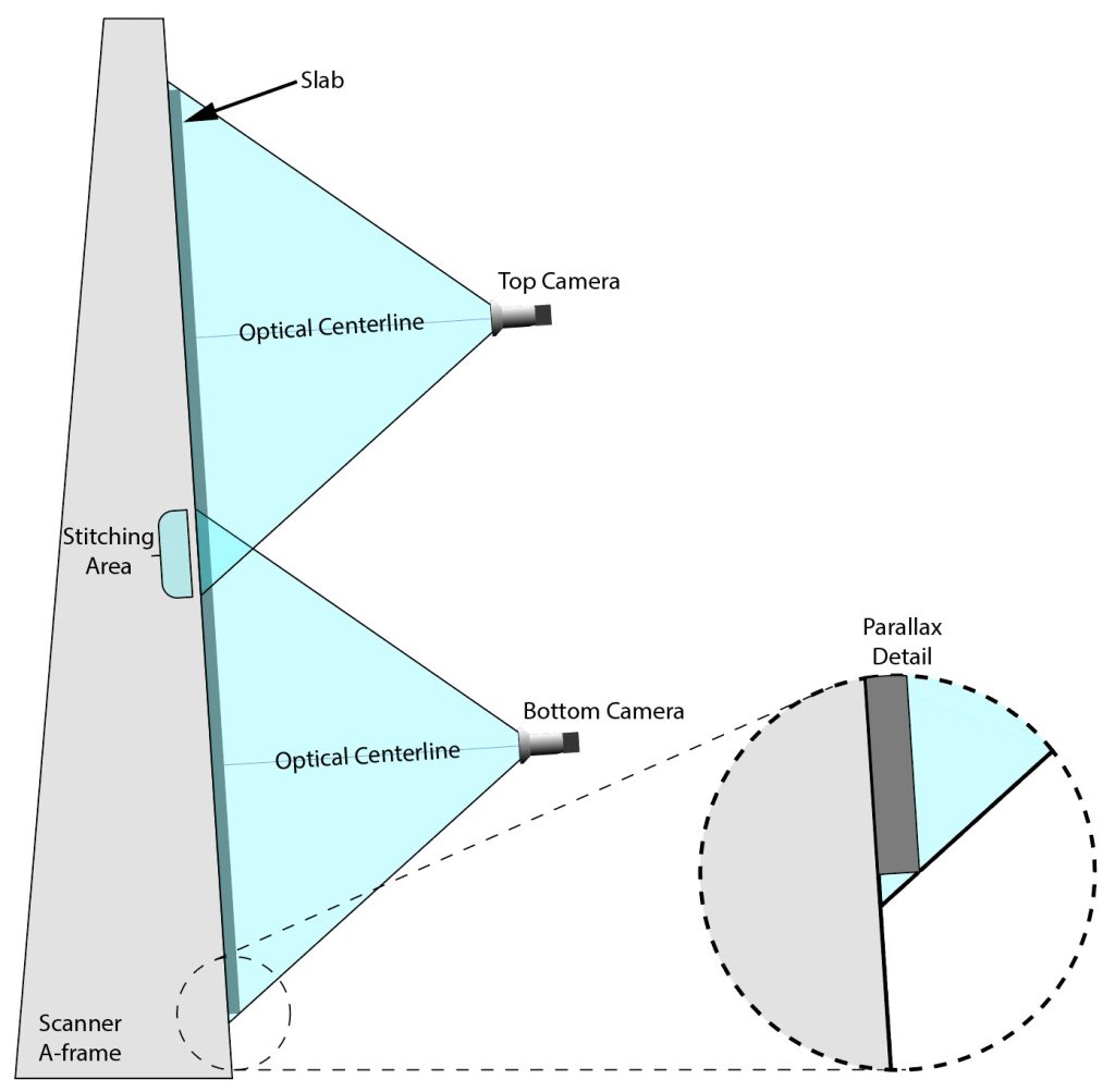 This diagram illustrates the general layout of a scanner. The field of view of each camera overlaps at the center. This is the “Stitching Area” where the two independent images must be merged for the final image of the entire line scan.
Stitching
There are various methods of stitching the images at the overlap area of the cameras. One method is to look for similarly colored pixels from the bottom area of the top camera and the top area of the bottom camera. When similar pixels are found the images are moved together and blended in the overlap, based on the similar pixels. This works reasonably well, but can fail if there is not enough color information at the overlap (for instance if the overlap area is a uniform color).
This is not the method used on the Stone Vision scanner. The Stone Vision scanner implements a calibration bar that is imaged on every scan. The bar has a series of black dots that are a know distance apart. Based on a known thickness of slab, this calibration bar provides a mathematical method to determine the correct stitching line between the images. This works regardless of having enough detail to graphically stitch the images. More detail on the calibration bar and how it works is discussed below.
Parallax |
Definition: The apparent displacement, or difference of position, of an object, as seen from two different stations, or points of view. |
At the optical centerline of each camera, the thickness of the slab is not a issue. However as you progress toward the edge of the camera’s field of view, the thickness must be allowed for. If you look at the parallax detail in the diagram, you will see that at the edge of the field of view, there is a significant difference between the position of the from the camera’s view between the top and bottom of the slab. As previously noted, a good camera and lens with a “Flat field correction” will do a reasonable job of correcting for this difference. This explains why it’s important to specify the correct thickness when scanning a slab to arrive at accurate dimensions on the final image.
The Stone Vision scanner calibraiton bar has two depths, one at 6mm and one at 30mm. Each scan is auto-corrected for the parallax distortion at each of these depths, then interpolated between them for any thickness scanned between 6mm and 30mm. This allows for any additional corrections needed beyond what the camera and lens are inherently capable of.
The Software
Slabsmith
The Start
In the early fall of 2024 Slabsmith was approached by the USA Helios representative “Total Stone Solutions”, to gauge a potential collaboration to create the next generation of slab scanners. SLAB VISION is the result.
Slabsmith was first released in 2005 and has been constantly improved for over 20 years. Slabsmith is arguably the reason that creating digital slabs and doing digital layouts is now considered standard fare in the stone industry.
 Development Goals
Once we agreed to a collaboration, with Helios building the hardware, and Slabsmith in control of the image processing. Slabsmith applied our experience in slab imaging to the unique needs of a scanner. This lead to the following goals.
- Industry leading dimensional accuracy
- Industry leading color accuracy and repeatability
- Extremely low maintenance and downtime
Each of these goals are intertwined in the approach Slabsmith implemented. The key to achieving these goals is a custom designed calibration bar and advanced software programming.
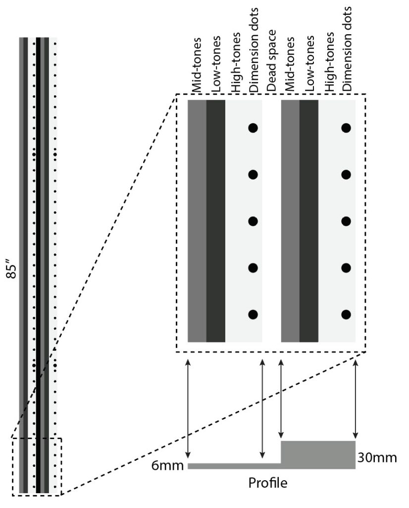 The Calibration bar
The calibration bar is 85 inches long in the scan line axis and 170mm wide. It is split into two different levels, one at 6mm and one at 30mm.
Each of these levels contains three color bars, Mid-tones, Low-tones and High-tones.
Each level also includes is a series of 10mm black dots spaced 50mm apart.
The combination of these features allows for continuous calibration (literally every time a scan is intiated).
What is calibration?
As a general description, calibration means taking a known quantity and conforming to it.
In this case the calibraiton bar is the known quantity. Slabsmith knows exactly what it is supposed to look like, and makes adjustments on every scan to allow for any minor changes that might take place.
This includes even minor differences such as the change in the intesity of the lighting with different slab thicknesses. (The further away from the source light, the less bright the light).
 What does the calibration bar and software allow for?
- Varitions due to slab thickness – including:
- Lighting intensity
- Dimensional accuracy
- Mis-alignment or rotations of the cameras
- Changes in the LED lighting
- The color of the source light will change with age
- Individual lights on the LED strip can be slightly different from each other or one may even ‘burn out”.
- Camera sensor variations –
- Individual pixels on the camera sensor are slightly different in their abilities due to manufacturing varations.
- Temperature of the camera sensor. Sensors are only repeatable at when operated at the same temperature each time.
What are the ramifications?
Very low downtime. The scanner is calibrated with every scan. Everything has been designed to keep you running.
Color accuracy – The color bars allow Slabsmith to build a color curve for every pixel on the scan line. This ensures consistent and repeatable color, even as the lighting changes or the camera sensor varies. There is no need to make color adjustments for different materials, or for changes in the lighting over time and it means you can color match with confidence.
Dimensional accuracy – The dimension dots provide a mathimatical and geometric method to guarantee the highest dimensional accuracy at any slab thickness. It also allows for minor mis-alignment of cameras without the need for factory support.
What are the results?
The highest color and dimensional accuracy of any scanner, with the lowest need for maintenance and support. All controlled directly within Slabsmith, the deepest, most powerful and easiest to use software in the stone industry.
What’s next?
Automatic slab thickness calibration – In the coming months, 3D mapping of the slab surface will be added to the STONE VISION scanner. This is to further insure the best dimensional accuracy when scanning a slab that may be warped. In other words, if the slab thickness relative to the cameras changes throughout the scan, it will cause some dimensional inaccuracies.
When the 3D mapping is added, you won’t even need to enter a slab thickness, it will be determined automatically during the scan and dimensional adjustments will be applied as the slab thickness varies anywhere on the slab.
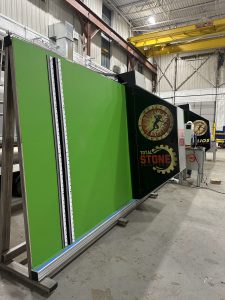
The Hardware
Helios “STONE VISION” scanner
It’s not just the software that makes the STONE VISION scanner next generation, it’s also the hardware.
What makes the STONE VISION scanner different?
Built in the USA – The STONE VISION scanner is the only scanner built in the USA, right in Detroit. While you won’t need much support, if you do, it’s close by.
Pain free setup and installation – This scanner is ready to go upon delivery. Drop it in place, hook up the power, start scanning digital slab directly into Slabsmith.
Largest vertical scanning area – The STONE VISION scanner has the largest scanning area of any scanner. Up to 85″ height is available (slightly less if you need slab rests for locating the slab on your saw).
Stainless steel frame – This scanner is made for your environment. Everything is stainless and aluminum, no rust or peeling paint.
Smart rail placement – The guide rail for the scanner head is on top of the frame, out of the way of potential damage while loading a slab.
Stand alone control desk – The machine is just the hardware. Control of the machine is a separate standalone standard PC, on it’s own desk. You can enter information into Slabsmith on the current slab while you are scanning the next slab! No need to wait for the scan to be completed. It’s a faster and more efficient workflow.
Since the PC is not contained within the scanner, if there is a problem with the PC, your monitor, your label printer… just replace it. We’ll install the software and you can get back to work.
For scanner pricing and delivery times, contact:

Nick Wadenstorer
Total Stone Solutions
www.Total-Stone.com
+1 248.804.1408